


2-4
Scanner Chapter 2
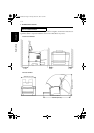
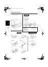
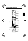
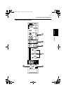
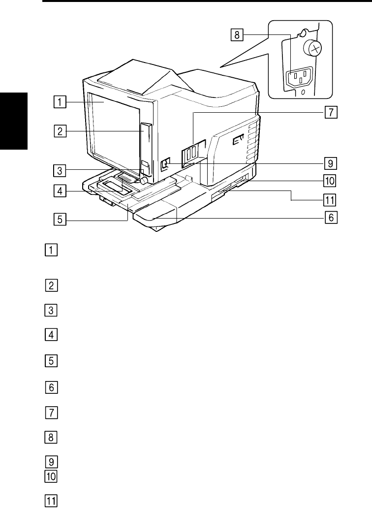
2. Parts of the SR24iT Scanner/Printer
Screen:
The image taken from the film is projected here for view-
ing. The frame on the Screen marks the data reading
range.
Control Panel:
Many operations are controlled from the keys and indica-
tors provided here.
Image Rotation Knob:
Used to turn the Prism Unit built into the Scanner, turning
the image on the Screen.
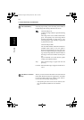
Projection Lens
(Optional):
Used to change the size and adjust the focus of the image
on the Screen.
Fiche Carrier 5
(Optional):
Supports the viewing of microfiche.
Projection Lamp Unit:
Contains are Mirror and Lens which projects the film
image onto the Screen.
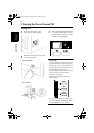
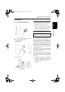
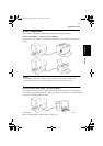
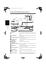
Connectors:
Provides connection points for the various options (Roll
Film Carrier and Controller).
Power Cord Socket:
Plug the power cord furnished with the Scanner into this
socket.
Power Switch:
Used to turn power to the unit ON and OFF.
Printer Connector:
Connects the scanner to the printer through an interface
cable.
SCSI Connector
Connects the scanner to the Personal Computer through a
SCSI cable. The PC Interface Cable Kit is required.
0820771003.book Page 4 Monday, March 19, 2001 2:49 PM